- Contact Person : Ms. OSN Cindy
- Company Name : Shenzhen OSN Power Tech Ltd.
- Tel : 86-755-25609941
- Fax : 86-755-25609943
- Address : Guangdong,ShenZhen,Room721 7th floor Gaobiao building,Cuizhu Road, Luohu District ,Shenzhen City
- Country/Region : China
12V/20A Protection Circuit Module For 4S/12.8V LiFePO4 Battery Pack


Related Product Searches:12V/20A Protection Circuit Module For 4S/12.8V LiFePO4 Battery Pack,High Quality,4s lifepo4 battery bms, 4slifepo4 battery bms,PCB/BMS/PCM-XGL65W40T5 (4S 20-20A)
12V20AH PCB/BMS/PCM Specifications For 4S /12.8V LiFePO4Battery Pack | |||
Model: PCB/BMS/PCM-XGL65W40T5 (4S 20-20A) | |||
No. | Test item | Criterion | |
1 | Voltage | Charging voltage | DC:14.4V 3.6V/Cell |
2 | Current | Current consumption for single cell | ≤50μA |
Maximal continuous Charging current | 20A | ||
Maximal continuous Discharging current | 20A | ||
3 | Over charge Protection | Over charge detection voltage | 3.90+0.025V |
Over charge detection delay time | 0.5—1.5S | ||
Over charge release voltage | 3.80+0.05V | ||
4 | Over discharge protection | Over discharge detection voltage | 2.00+0.08V |
Over discharge detection delay time | 50-150mS | ||
Over discharge release voltage | 2.50+0.1V | ||
5 | Over current protection | Over current detection voltage | 0.15+0.025V |
Over current detection current | 60+10A | ||
Detection delay time | 5ms—15mS | ||
Release condition | Cut load, Automatic Recovery | ||
6 | Short protection | Detection condition | Exterior short circuit |
Detection delay time | 200-500us | ||
Release condition | Cut load, Automatic Recovery | ||
7 | Resistance | Protection circuitry (MOSFET) | ≤20mΩ |
8 | Temperature | Operating TemperatureRange | -40~+85°C |
StorageTemperatureRange | -40~+125°C | ||
9 | Size | L65*W40*T5mm | |
10 | Motor Power | 250W or below | |
Main Functions:
The product has 6 main functions: over charge, over discharge, over current, short circuits, balancing and low-current lock.
1. Function of over charge protection: once voltage of any battery in the pack gets higher than the over charge protection point, charge cuts off to ensure all batteries work within the over charge protection point.
2. Function of over discharge: once voltage of any battery in the pack gets lower than the over charge protection point, discharge cuts off to ensure all batteries work beyond the over charge protection point.
3. Function of over current: during the discharge process of battery pack, once discharge current gets over the set over current protection point, output cuts off to ensure battery pack works within the safe limit of current.
4. Function of short circuit protection: once battery pack’s output port appears the condition of short circuit, it cuts off to ensure battery group not to be damaged because of short circuit.
5. Function of voltage balancing: in the late charging period of battery pack, voltage difference that appears during the using process of each battery could get balancing revised to ensure battery pack’s capacitance.
6. Function of low-current lock: series connection of low-current lock gets reserved and low current controls on-and-off of the main high current to make it safer and more convenient.
Usage and Attention:
1. Please strictly follow the directions to connect the PCB to the battery. Usually there's voltage in the battery at all time, so operator should connect one single line after other starting from terminal B, following the order from low voltage to high voltage, otherwise it can cause irreparable damage.
2. During the installation, pay attention to small metallic particles that can stick to the protection board.
3. Follow the standard rules when making connections between the protection board and the lithium-ion battery. Operator should not run any wire across the back of the protection board. Keep them along the side of the board instead.
4. When setting up the protection board, be sure to use a hard epoxy board as an interlayer, to prevent short-circuit caused by the components on the back of the protection board.
5. Both resistive load and inductive load can be used to test battery packs that use this PCB, but not electronic load. Testing with an electronic load will lead to the breakdown of the MOS components on the protection board.
6. Select proper wire gauge to prevent temperature increase from high discharge current (when wire gauge is too high) and excessive voltage drop (when wire gauge is too low).
7. When the PCB is to be installed inside the battery's housing, the user must fully take heat/electric insulation and tightness into account to prevent internal short circuit.
8. Keep any fully charged battery away from children.
9. If any abnormality is detected during use, please stop using the product immediately and notify professional technician to conduct inspection and maintenance.
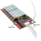
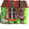
Ways of line-connection:
The following procedures should be accorded with the referrence of drawings:
1.Weld a power supply line with the proper diameter from the B- port of guard shield and connect it with negative pole of battery pack (B-);
2.Connect line 1 signed in the line-connection drawing with the second battery's pole in the battery pack;
3.Connect line 2 signed in the line-connection drawing with the third battery's pole in the battery pack;
4.Connect line 3 signed in the line-connection drawing with the fourth battery's pole in the battery pack;
5.Connect line 4 signed in the line-connection drawing with the fifth battery's pole in the battery pack;
6.Connect the red line on the highest position signed inthe line-connection drawing with the last battery's positive pole in the battery group;(different signal lines' connection could be operated with the above reference)7.A power supply line with the proper diameter led from the battery pack's positive pole (B+) and another similar line led from the guard shield's P- should be respectively connected with the positive and negative poles of the load.8.A power supply line with the proper diameter led from guard shield's C- and another power supply line led from the battery pack's positive pole (B+) should be respectively connected with the negative and positive poles of the charger.
12V/20A Protection Circuit Module For 4S/12.8V LiFePO4 Battery Pack